Table of Contents
- Author(s) of this documentation:
- Bertrand Kerautret and Jacques-Olivier Lachaud.
Part of the Topology package.
This part of the manual describes how to use the helper class Surfaces to build digital surfaces, closed or open, or contours within digital surfaces. A lot of the ideas, concepts, algorithms, documentation and code is a backport from ImaGene.
All the code presented here require:
- Note
- This class is useful if you wish only to obtain the set of surfels of a given digital surface or if you wish to obtain 2D contours (in 2D or 3D). If you require more advanced operations on surfaces (for instance using afterwards the topology defined on the surface), it is better to wrap a DigitalSurface object around your surface of interest, see Digital surfaces.
The 2D case: the boundary is a sequence of cells
The surfaces classes offers the possibility to extract an open or closed contour as a sequence of surfels obtained from a DigitalSet and a starting surfel. The full code of this example is available in file ctopo-2.cpp .
The first step to extract the surfel boudary of a 2D digital set is to obtain an initial boundary surfel:
The first surfel can also be displayed in red with Board2D:

Then you can extract the sequence of consecutive surfels:
@code
 std::vector<Z2i::SCell> vectBdrySCell;
 SurfelAdjacency<2> SAdj( true );
 Surfaces<Z2i::KSpace>::track2DBoundary( vectBdrySCell,
                                         ks, SAdj, set2d, aCell );
@endcode
and display it:
@code
 GradientColorMap<int> cmap_grad( 0, vectBdrySCell.size() );
 cmap_grad.addColor( Board2D::Color( 50, 50, 255 ) );
 cmap_grad.addColor( Board2D::Color( 255, 0, 0 ) );
 cmap_grad.addColor( Board2D::Color( 255, 255, 10 ) );

 unsigned int d=0;
 std::vector<Z2i::SCell>::iterator it;
 for ( it=vectBdrySCell.begin() ; it != vectBdrySCell.end(); it++ ){
      board<< CustomStyle((*it).className() ,
                          new CustomColors( Board2D::Color::Black,
                                            cmap_grad( d )))<< *it;
      d++;
}
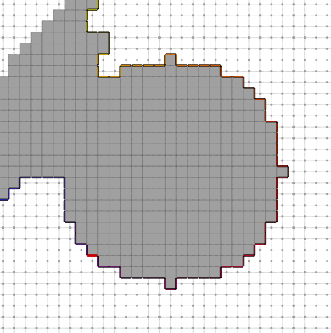
You will obtain the following ordered sequence of surfels:

The resulting sequence of surfels does not necessary present an open contour (try for instance image "samples/circleR10modif.pgm"):
Tracking a 3D boundary to build a surface.
With only few modifications we can apply the same extraction on 3D surfel set. The file ctopo-2-3d.cpp shows the same previous example adapted in 3D.
with the same code we can get a surfel boundary:
From this SCell all the surfel connected sets can be extracted:
To see both initial surfel and the surfel set, we can use the transparent mode:
To avoid surfel superposition we need to increase with a small shift the surfel size, for this purpose you can add the following key:
or use the special mode "Highlighted" which increase automaticly the surfel size.
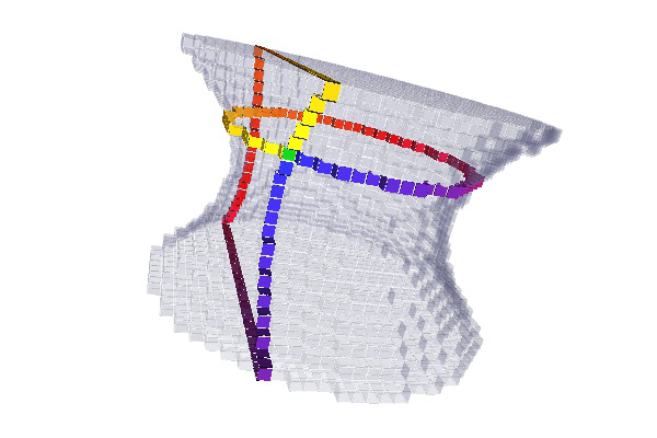
You can obtain for instance the following visualisation:

Since in 3D there are several choice for the direction used to exctract surfel boundary, we can specify the constant direction need to drive the surfel extraction:
After extracting the two surfels cut you may obtain the following visualisation:
Extracting surface of connected components
The class Surfaces provides other useful function to extract connected boundary surfels from a digital set and given a surfel adjacency definition. The example 3dKSSurfaceExtraction.cpp shows an example of such an extraction.
From a domain we construct a DigitalSet inserting points under given conditions (see. 3dKSSurfaceExtraction.cpp for more details)
With this domain bounding points (p1, p2), a KhalimskySpace is constructed and a SurfelAdjacency definition is introduced.
Then we can extract all connected surfels from the digitalSet surface :
After processing a simple display of each resulting connecting component you can obtain such a visualisation:

Here since the last argument is set to true, the resulting SignedKhalimskySpaceND are signed in order to indicate the direction of exterior. You can also get the SignedKhalimskySpaceND with default sign:
and you will get the resulting cell display:

Filling oriented digital contours
The helper class Surface also proposes some methods to fill the interior/exterior of a digital set of 1-SCell which can be defined from an oriented FreemanChain. These methods can be usefull in particular to reconstruct images (as given for instance in the tool of freeman2pgm given in DGtalTools.).
The example ctopo-fillContours.cpp illustrates a basic filling with a shape containing a hole. The main steps to fill a contour represented by a FreemanChain are the following:
First we construct two FreemanChain to illustrate the fill with two different orientations:
To construct the set of signed SCell, we use the method getInterPixelLinels of FreemanChain class:
- Note
- The that the resulting Cell orientation is defined by convention such that a contour defined in the direct orientation will generate the fill of the interior of the shape (with the uComputeInterior method) while the indirect orientation should be used to define a hole (see example below).
Afterwards the region associated with the direct oriented contour (fc1) can be filled by using the method uComputeInterior with the parameter empty_is_inside set to false. This parameter choice is justified since here a line which does not contain any boundary element is necessary at the outside of the contour.
The interior Cells obtained from such a contour are illustrated here:

We can also reconstruct region with hole by using a contour in the indirect direction. For instance we can define
And after adding it to the previous set boundarySCell you will obtain such a display:

- Note
- From an indirect oriented contour you can also fill both the interior and exterior: For the interior region, the parameter empty_is_inside parameter is set to true since a line without boundary element will correspond to the interior of the shape (since the contour is given the indirect orientation). In the same way, the parameter empty_is_outside is set to false. You will obtain such a representation:BoolImage2D interiorCellHoleImage( imageDomain );BoolImage2D exteriorCellHoleImage( imageDomain );Surfaces<DGtal::KhalimskySpaceND< 2, int > >::uFillInterior(K, functors::SurfelSetPredicate<std::set<SCell>, SCell>(boundarySCellhole),interiorCellHoleImage, 1, true);Surfaces<DGtal::KhalimskySpaceND< 2, int > >::uFillExterior(K, functors::SurfelSetPredicate<std::set<SCell>, SCell>(boundarySCellhole),exteriorCellHoleImage, 1, false);
 Filling interior (lightgray) and exterior (dark gray) of indirect oriented contour.
Your challenge
Now you are able both to extract a set of contours and to fill contours. The exercise is now to reconstruct an image from a given set of contours.
Exercise
You challenge is to code:
- The load the set of all the Freeman Chains given in a text file.
- Transform Freeman Chains into signed cells of KhalimskySpaceND (SCell).
- Reconstruct an image associated to its Freeman Chains by filling.
- Identify image hole and fill it with specific gray level.
- Exporting resulting image in pgm format.
Hints
- The class PointListReader contains various method to read input from text file. In particular you can use the method getFreemanChainsFromFile (step 1). To reconstruct the image you can first define some types from KhalimskySpaceND with also the resulting image: typedef KhalimskySpaceND<2, int>::SCell SCell;typedef DGtal::ImageContainerBySTLVector<Z2i::Domain, unsigned char> Image2D ;Aim: This class is a model of CCellularGridSpaceND. It represents the cubical grid as a cell complex,...Definition: KhalimskySpaceND.h:394
- Note
- To apply the reconstruction, you can use the following file given in this path: DGtal/examples/samples/contourS2.fc
- Then you will also need to transform the freeman chain into signed cells (SCell) given in the KhalimskySpaceND. For this purpose you can use the FreemanChain method getInterPixelLinels (step 2).
- For the step (3) you have first to save on cell by exploiting the filling described in the previous section. Then you can update the resulting image in particular with the method uCoords from KhalimskySpaceND which allows you to recover the coordinate in image domain. For instance to set to 255 the image pixel associated to the Cell c, you can do: imageResult.setValue(ks.uCoords(*it), 255);
- To identify the holes of step (4) you have to exploit the contour orientation. For this purpose you can use the method ccwLoops of the FreemanChain class.
- Note
- We recall that by convention holes are oriented in the CW direction (or indirect order).
- Finally you can export the result just by including the GenericWriter and the flux operator: #include "DGtal/io/writers/GenericWriter.h"...yourImage >> "yourImageName.pgm";
Result
If you succeed the exercise you will obtain the following pgm image:
